Length cutting and assembly information for technical hoses and cable protection hoses
Work safety notes
Work safety regarding working with a knife:
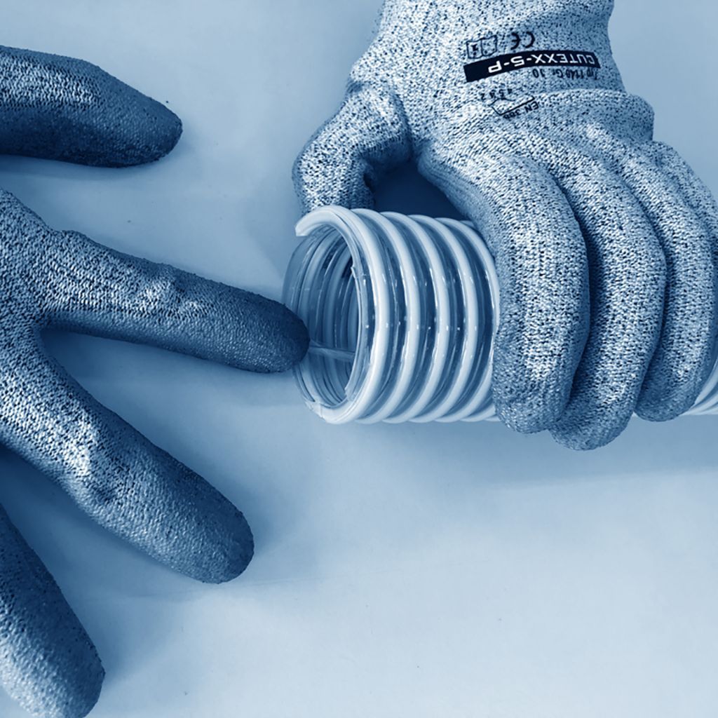
Always wear cut-resistant gloves
Arms must be held in parallel position. Do not cross arms while cutting
Hold the hose a minimum safe distance of 10cm from the cutting tool
Technical hoses
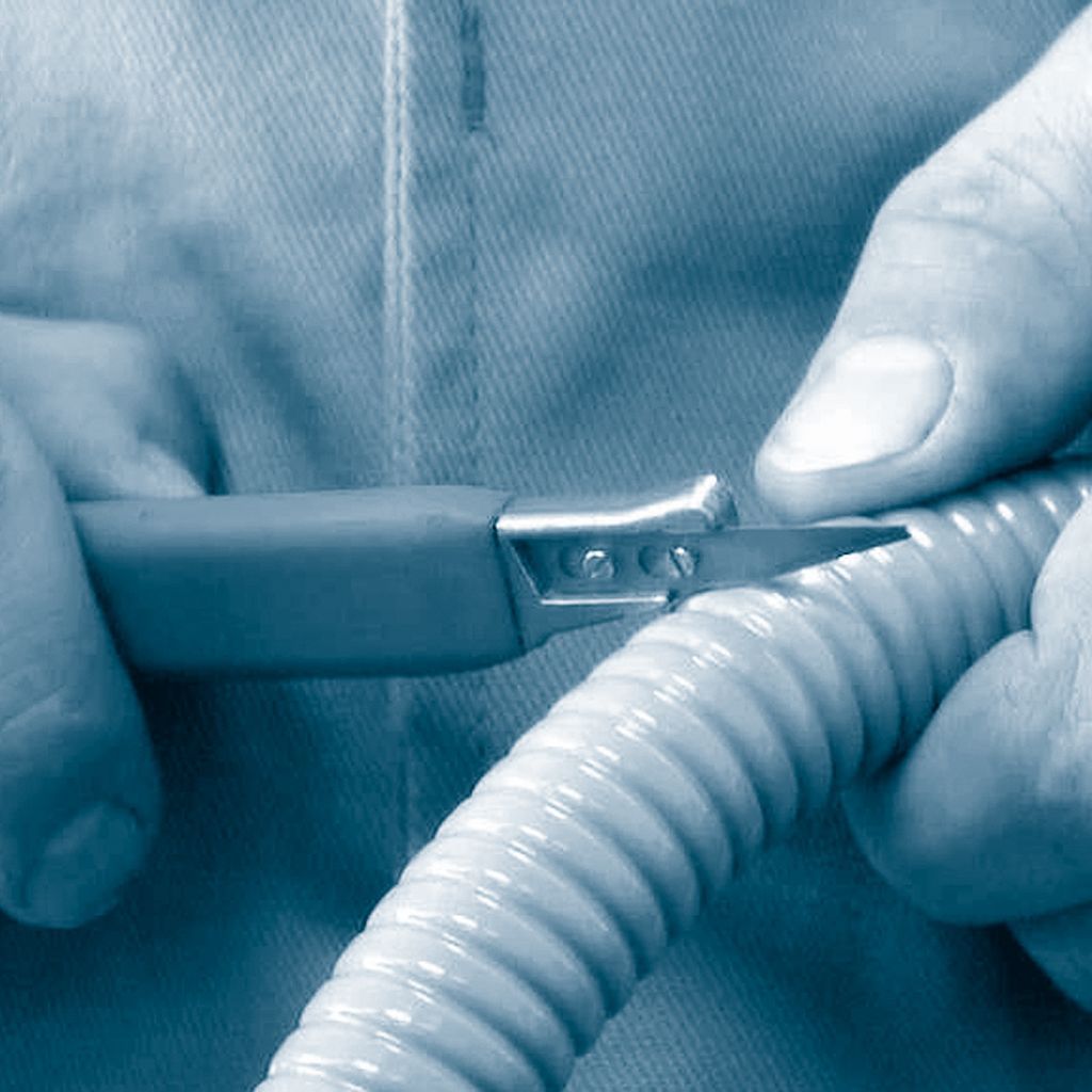
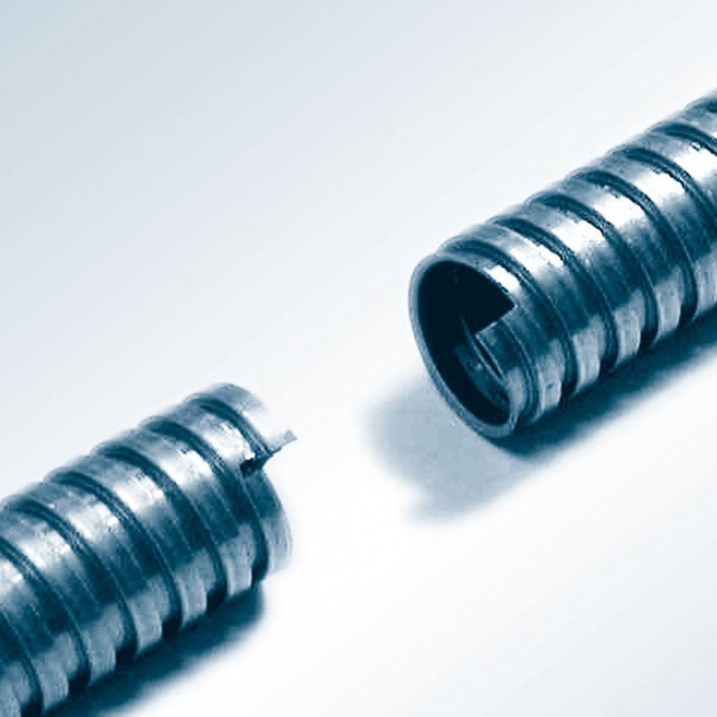
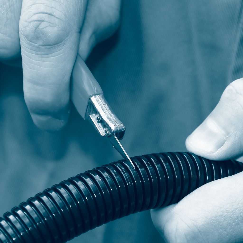
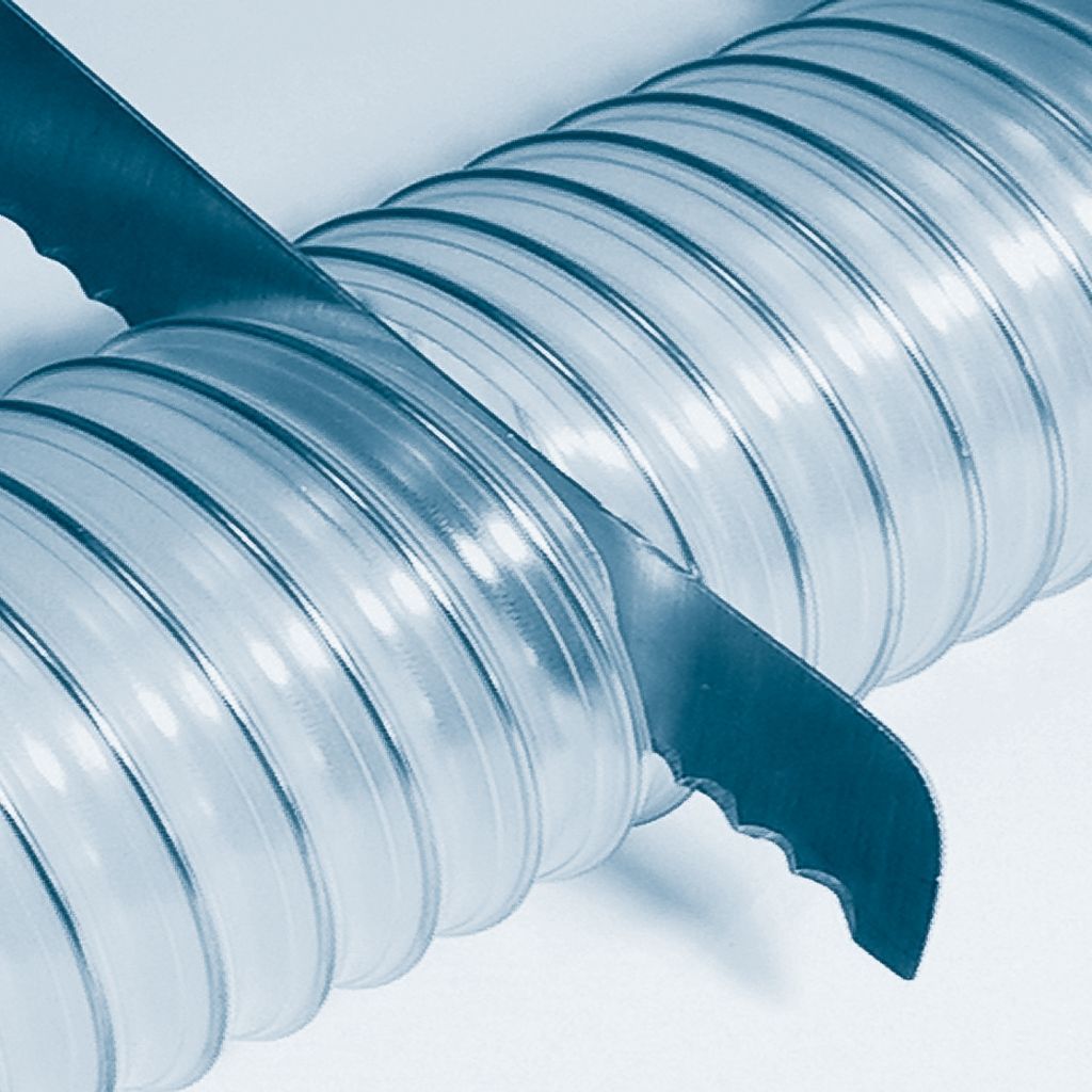
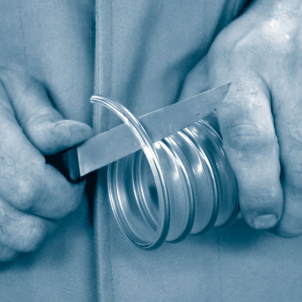
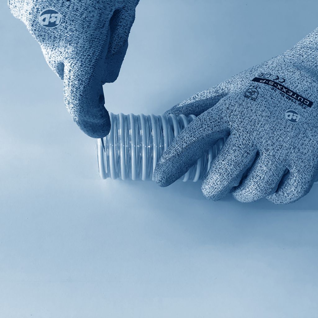
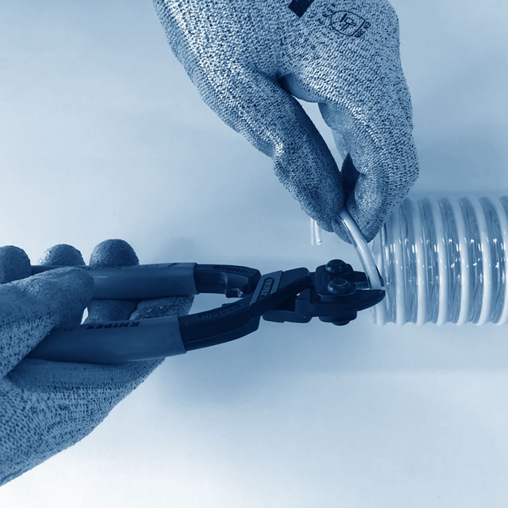
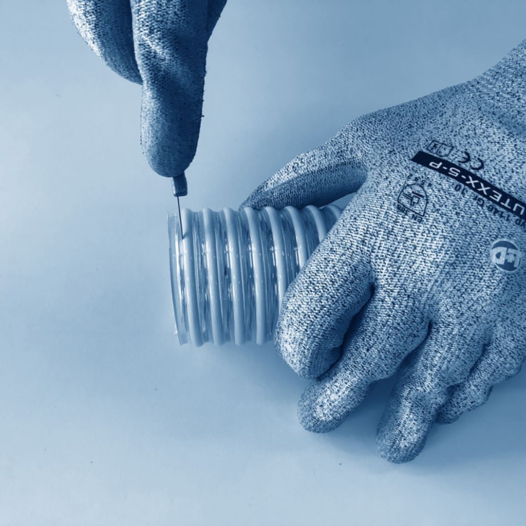
Cutting of spirally reinforced plastic hoses
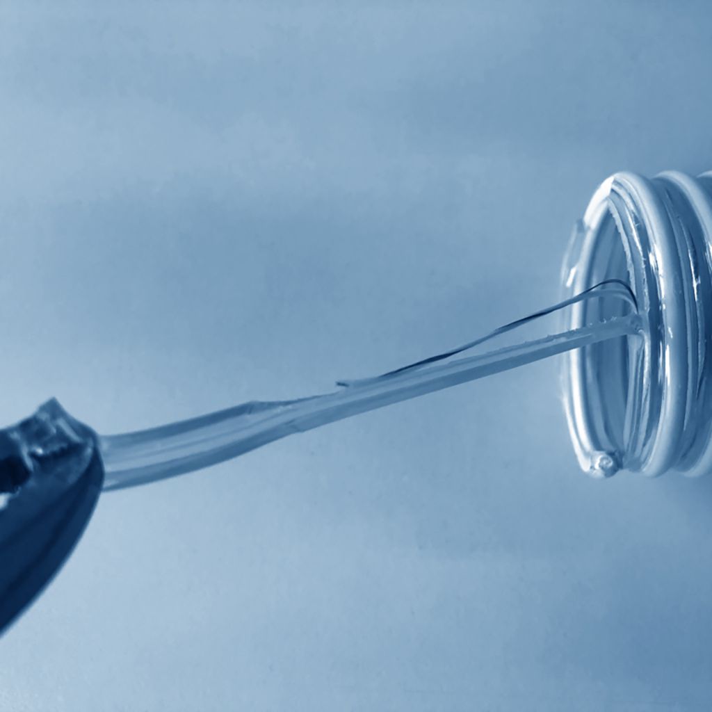
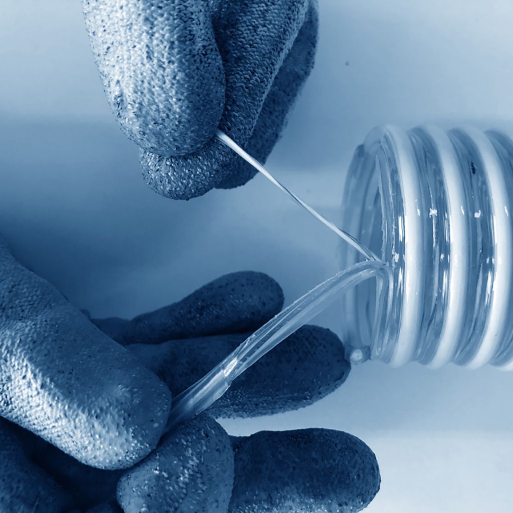
Step 1: Cut through the hose material, preferably with a serrated knife
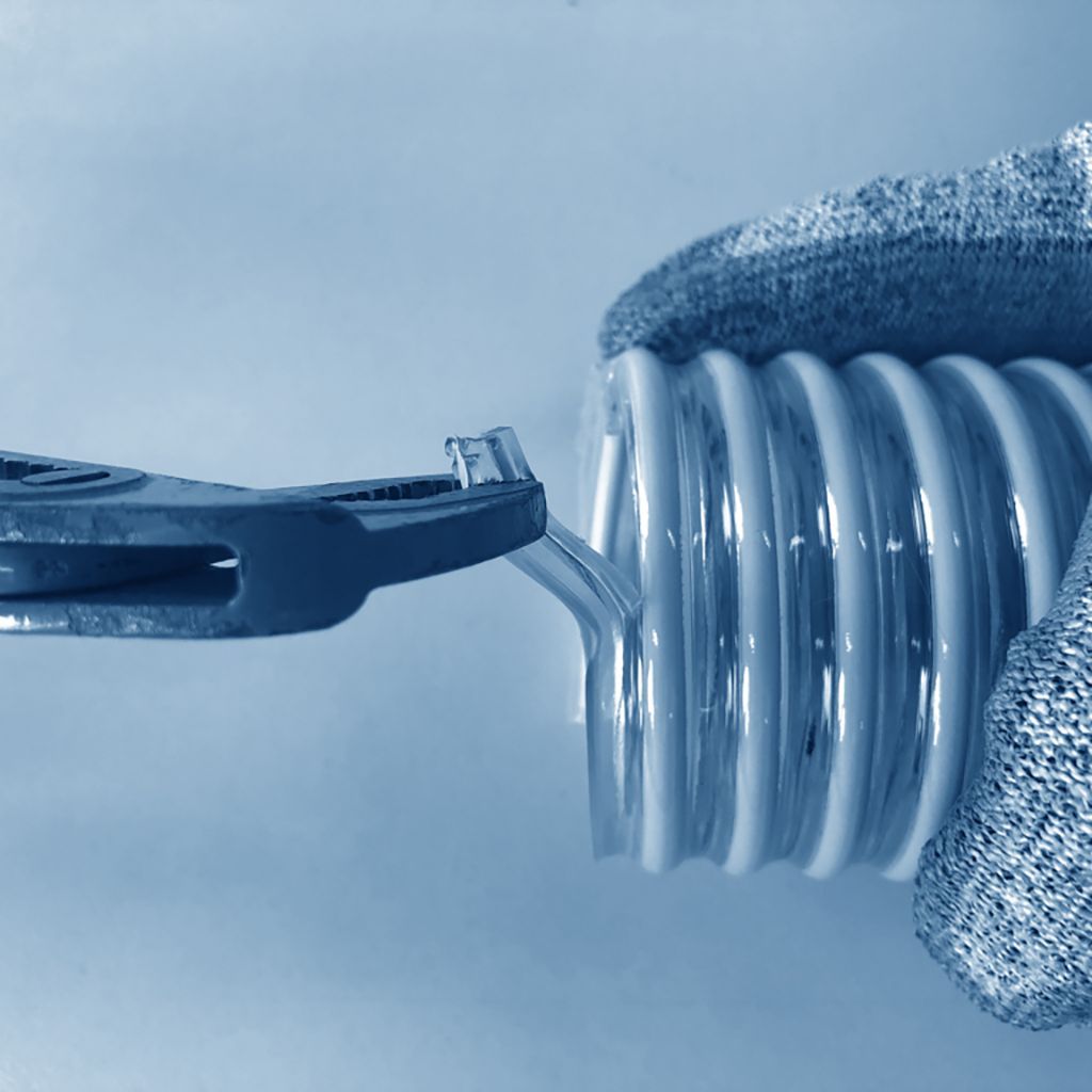
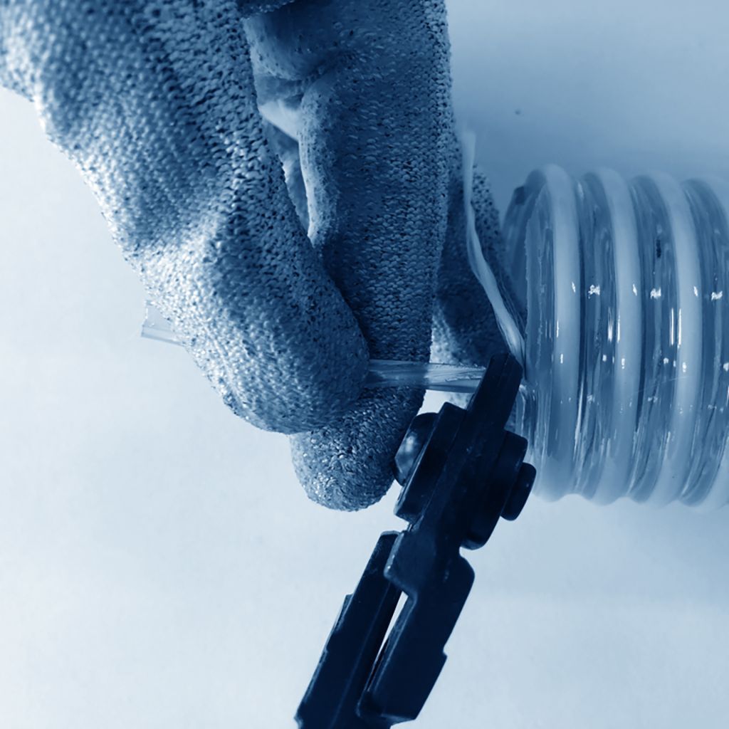
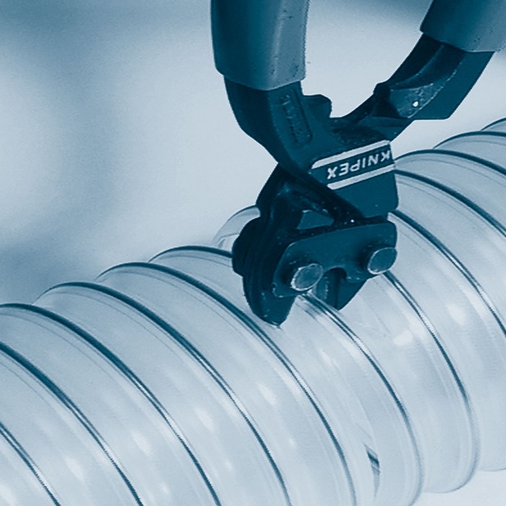
Step 2: Snip the supporting spiral with wire pliers
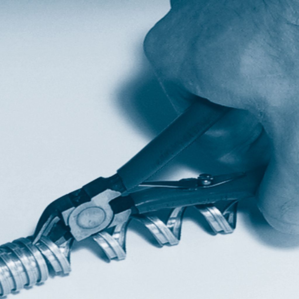
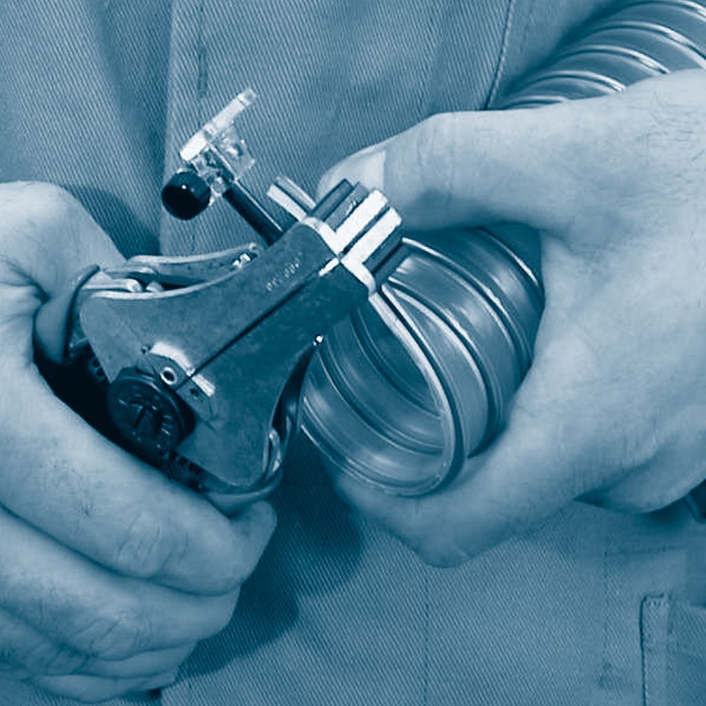
Cutting of the metal hoses 375 - 377
Step 1: Fix the ends with rivets or by soldering
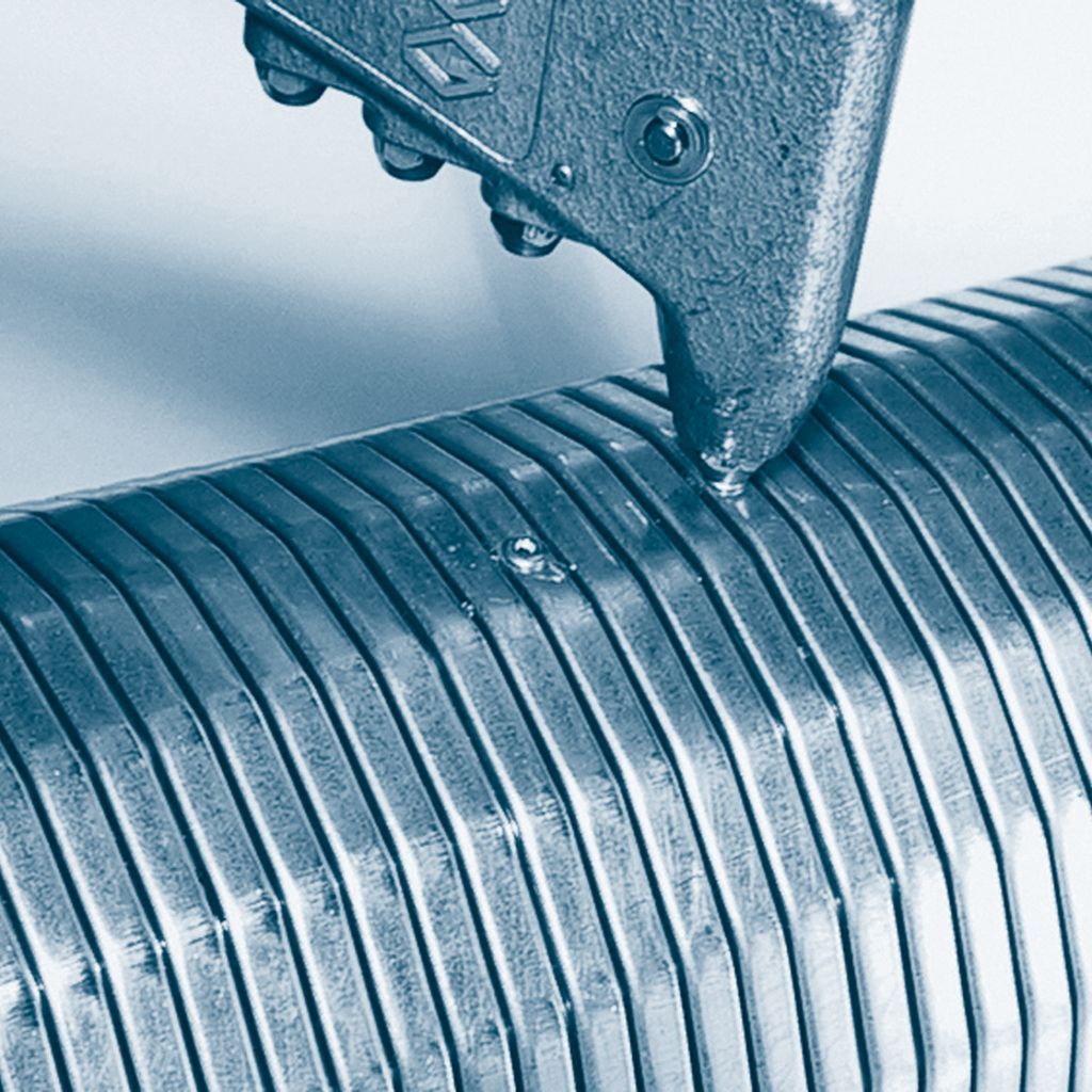
Step 2: Lever out the profile with a screw driver
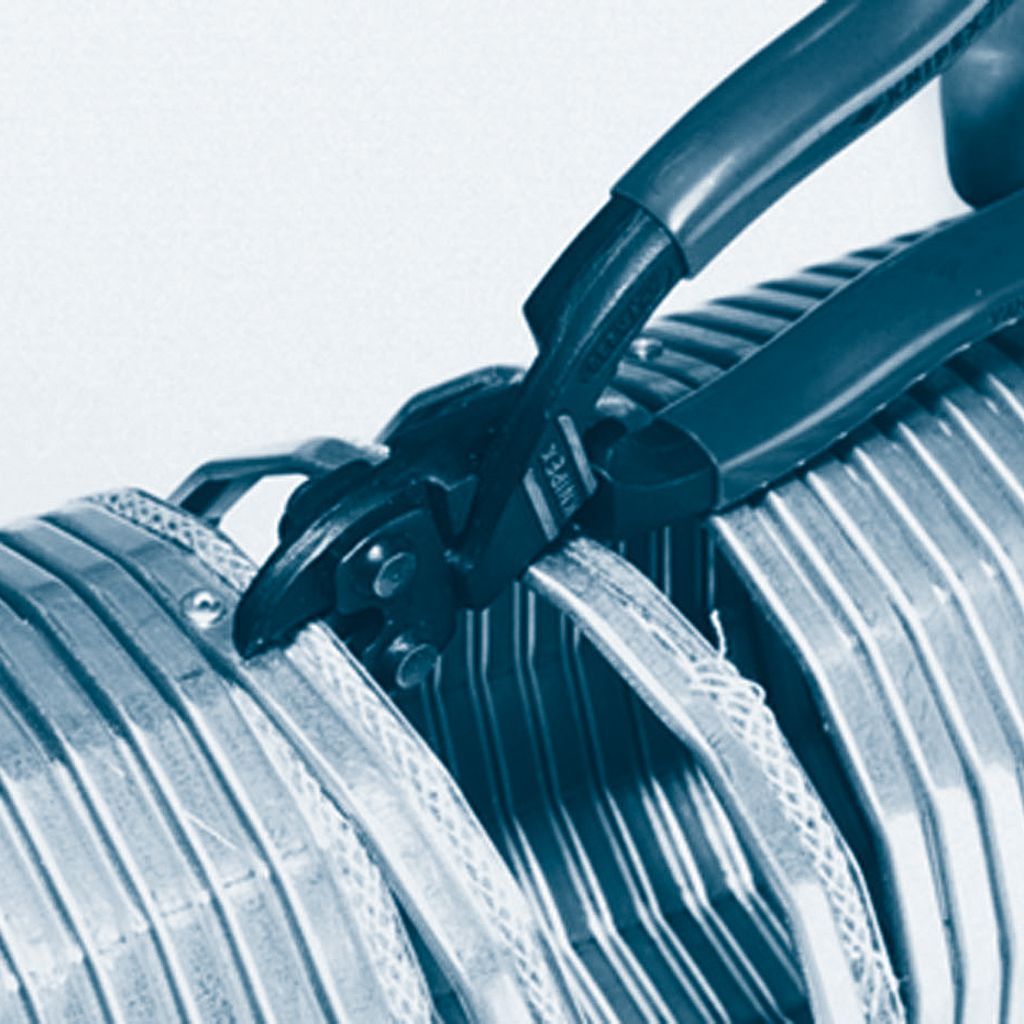
Step 3: Cutting of the protruding profile with a shear blade or diago-nal cutting pliers
Grounding for protection against electrostatic charging
Effective and permanent grounding of all installation components (including hoses and hose fittings) provides protection against disruption to media flow or ignition of explosive atmospheres. Please note our corresponding data sheet electrostatic charging.
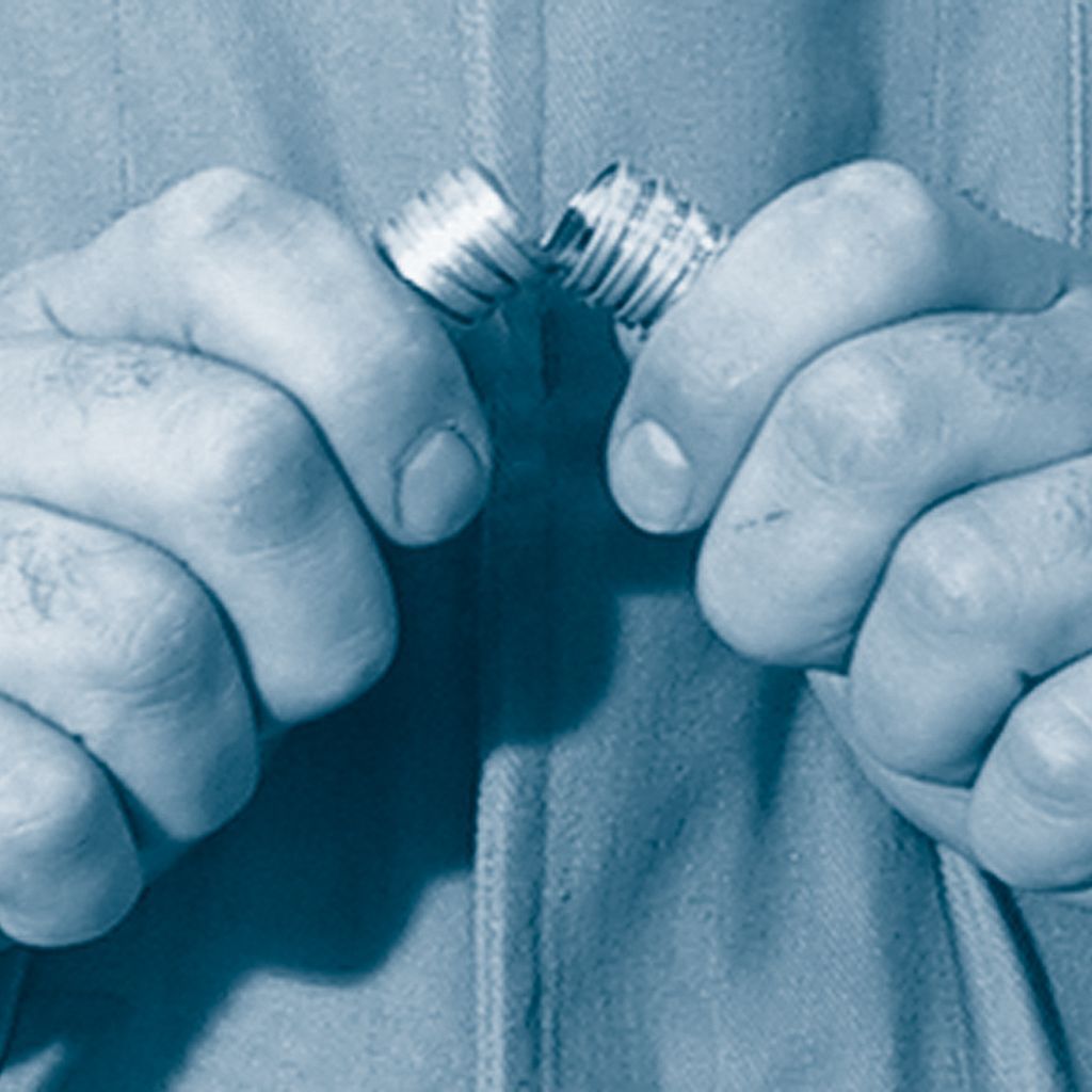
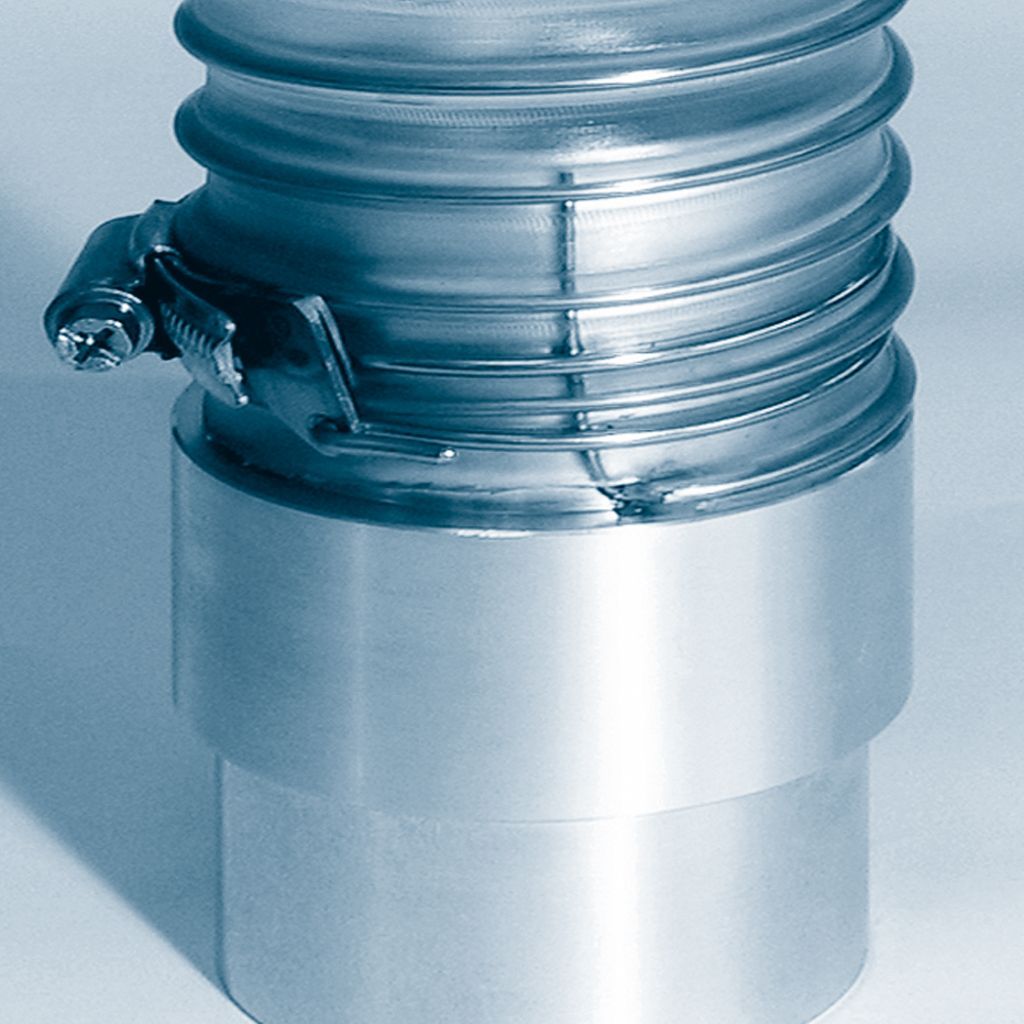
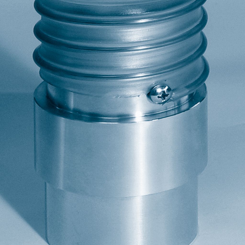
Variant 1: Expose the spiral, bend it to the inside and insert the conductive hose fitting.
Variant 2: Expose the spiral and fix it, for example, by a rivet or screw.
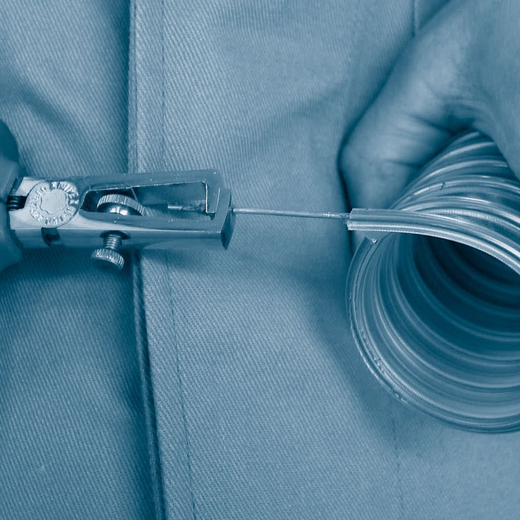
Strip insulation of AIRDUC® hoses
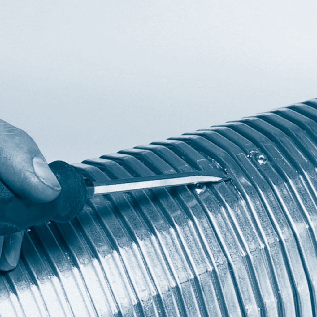
Step 1: Cut hose with a sharp knife along the steel wire.
Step 2: Remove plastic from around the wire with a wire stripper...
...or remove it more convenient with a precision insulation stripper.
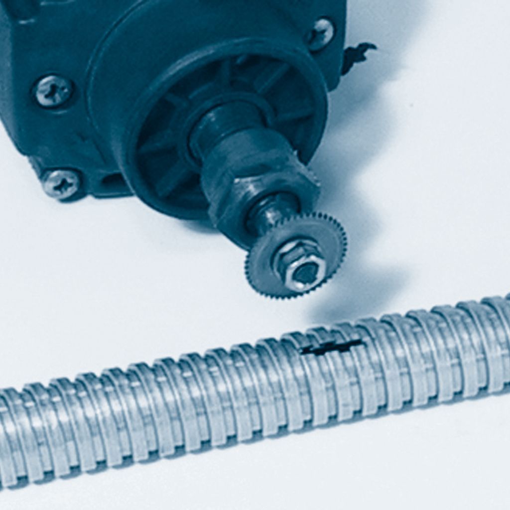
Pulling out the earthing wire of NORPLAST® PUR-C / PVC-C AS hoses
The copper grounding wire is integrated into the hose wall between the hard-plastic reinforcing spirals.
Step 1: Cut half of a circumfer-ence of the hose wall next to the grounding wire. The grounding wire stays on the residual part of the hose.
(Detail view)
Step 2: Then, cut-off the pro-truding hard-plastic spiral with a side-cutter.
Step 3: Cut round ¼ of the hose wall next to the wire, leaving the wire in the detached part of the hose wall.
(Detail view)
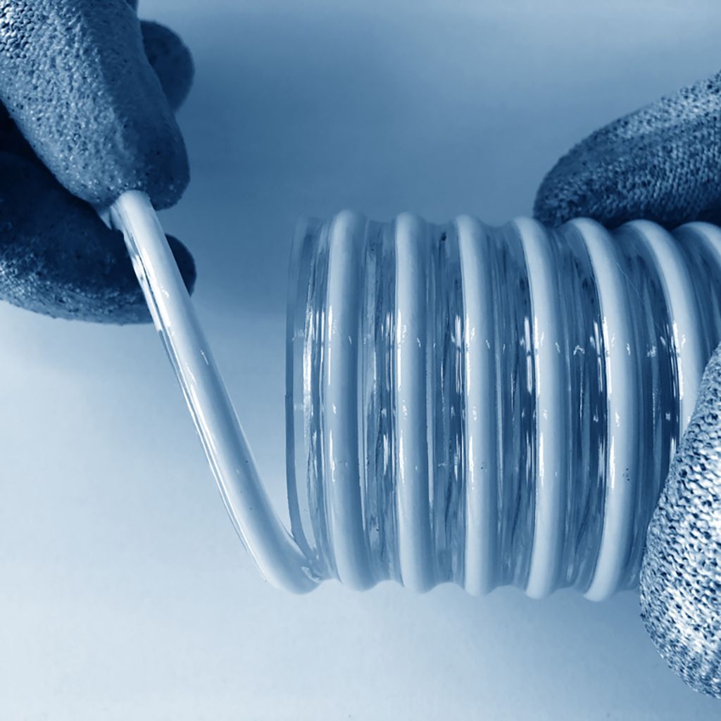
Step 4: Grip the detached strip of hose wall and pull until the grounding wire is exposed.
Step 5: Separate the grounding wire and hose wall by carefully pulling them apart. Cut off the loose end of the hose wall with the side-cutter.
For grounding, bend the ground-ing wire into the hose and insert the conductive hose fitting to be earthed.
Notes on electrical grounding:
The grounding wire should be electrically grounded on both ends of the hose.
After grounding, measure the electrical resistance between the two grounded hose ends. The electrical and surface resistance should measure <109 Ohm.
Please take into consideration any special regulations, local laws or provisions that are applicable to your situation or application.
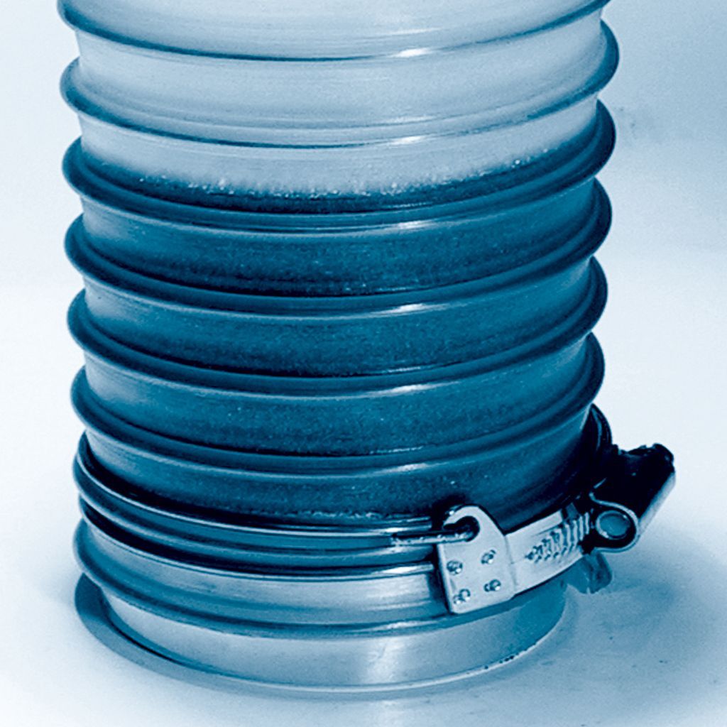
Leak-proof assembly
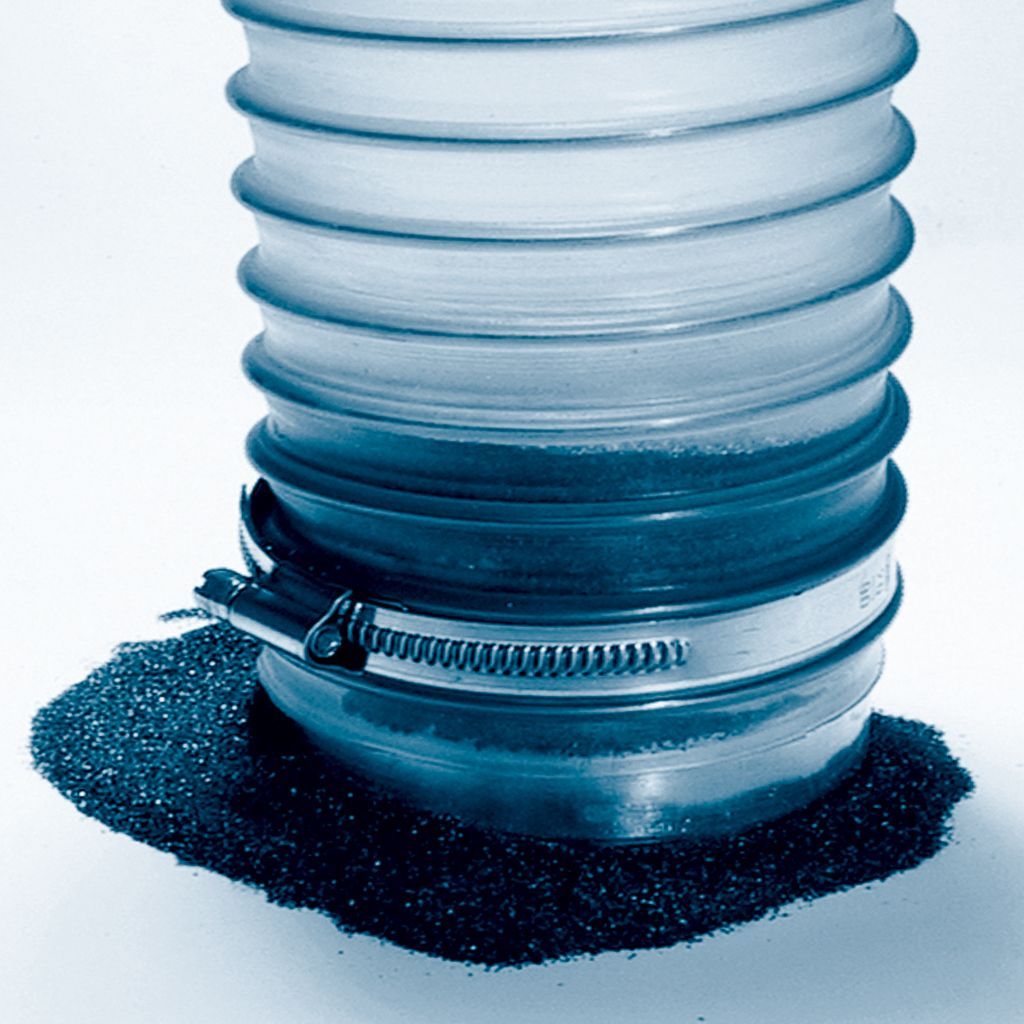
A satisfactory seal can be assured when using our specially-developed spiral hose clamps. Leaking media can pose a threat to people and the environment, as well as causing process problems and reduced efficiency.
Leak-proof assembly using our original accessories.
Significant leakage resulting from use of conventional hose clamps.
Cable protection hoses
Cutting of bare or plastic coated cable protection hoses of metal (types 101 – 109)
By bending:
Step 1: Cut the plastic mantle (if existing).
Step 2: Bend the metal hose.
Step 3: Cutting of the protruding profile with a shear blade or diago-nal cutting pliers.
By intersecting:
Step 1: Cut the plastic mantle (if existing).
Step 2: Bend the metal hose.
Step 3: Cutting of the protruding profile with a shear blade or diagonal cutting pliers.
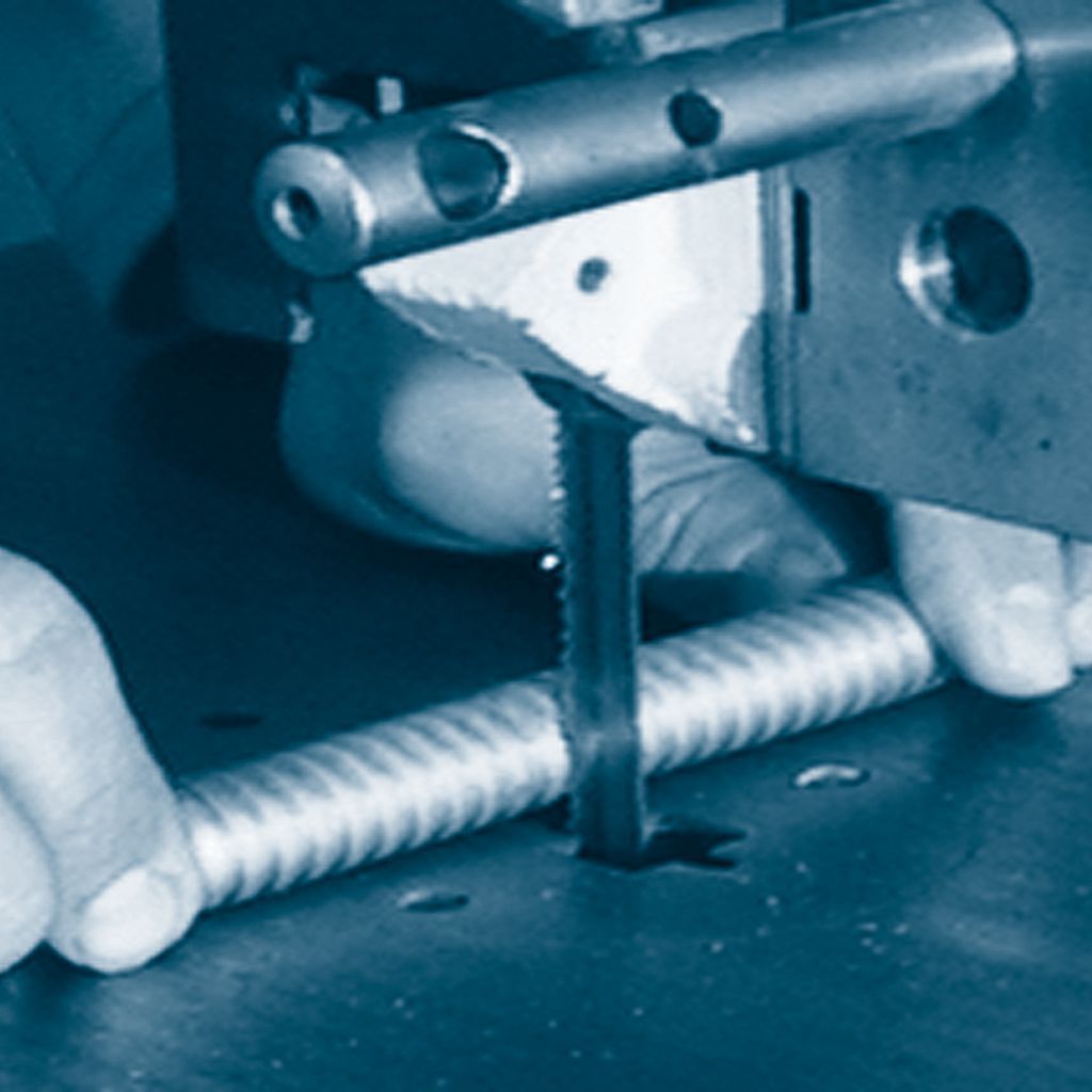
By sawing:
Step 1: Cut the metal hose on a belt saw at high cutting speed.
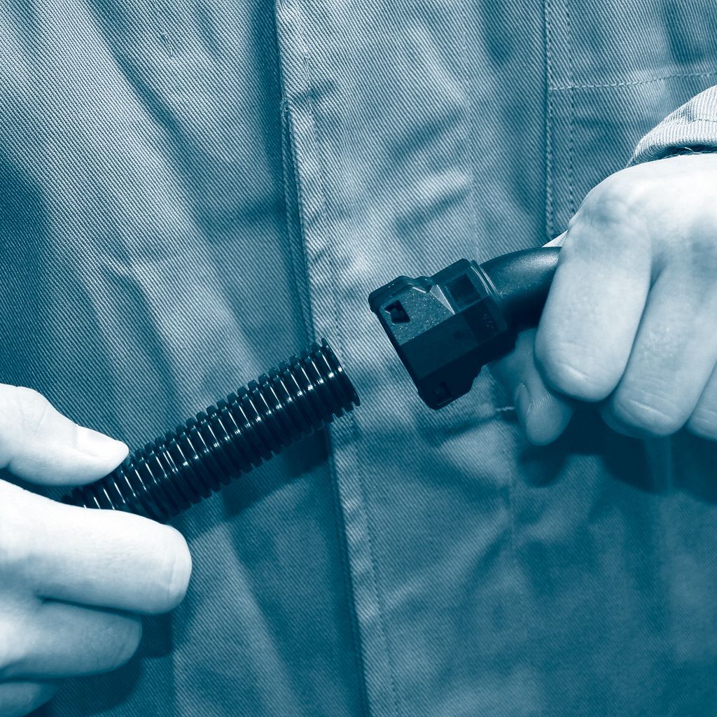
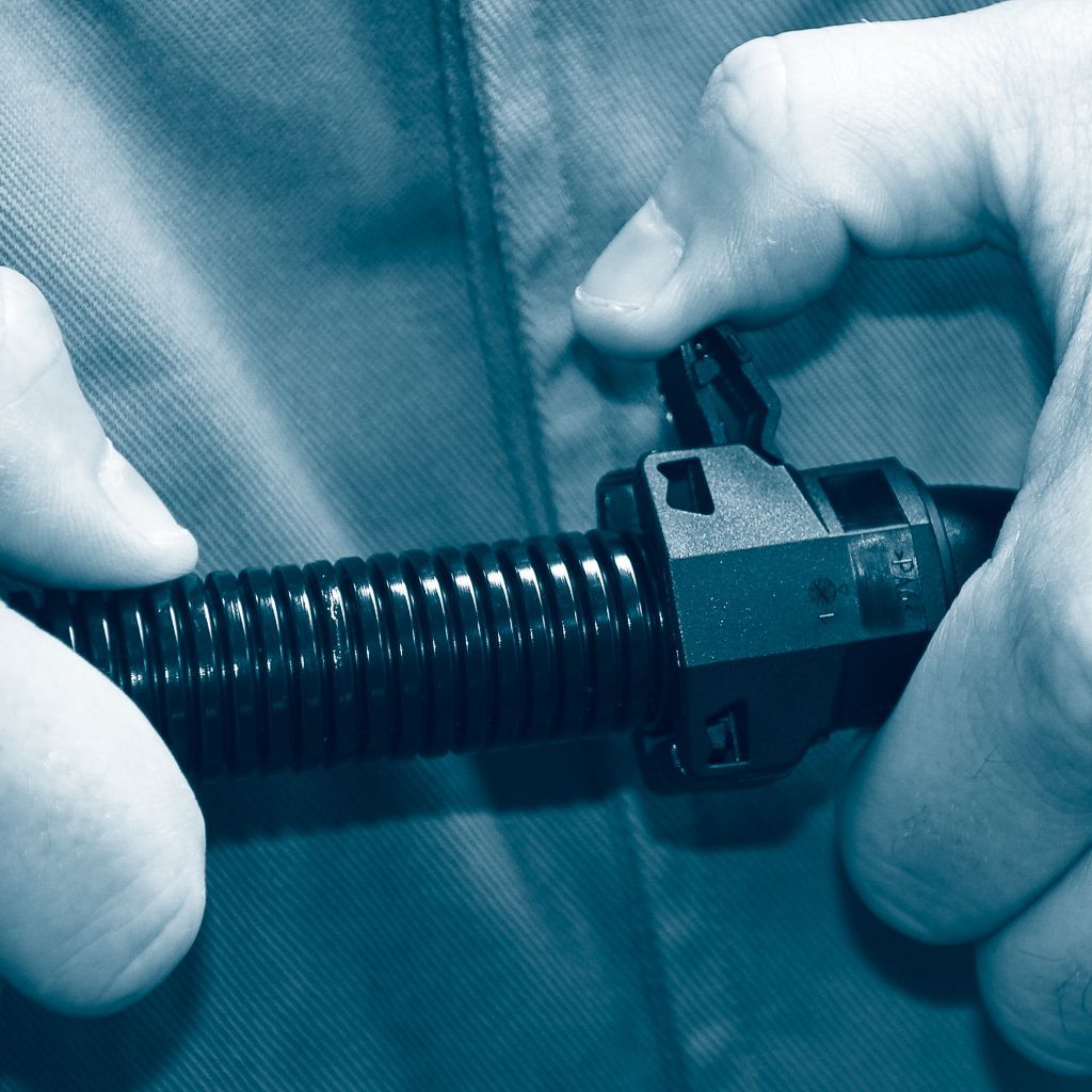
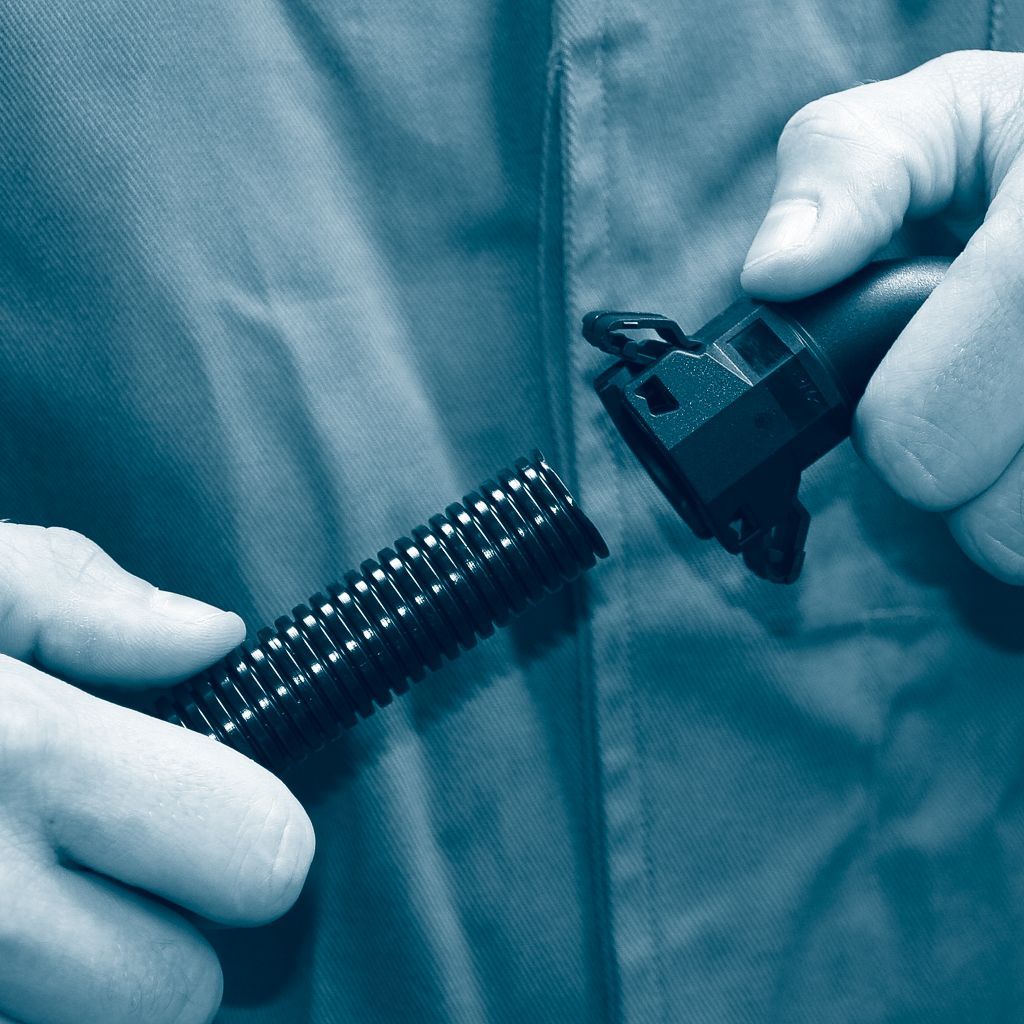
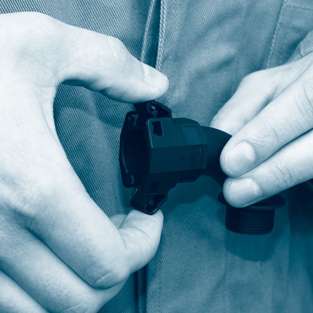
NORDUC® one hand assembly system
Due to the conic inside and the snap in hooks, the connector is universal suitable for different tube profiles. (Stand-ard-, Coarse- and UFW-profile) IP 65 is reached acc. to EN 60529/IEC 60529 in this combination. The IP 68 rate is attained with an O-ring sealing, mounted in the first wave trough of the tube (trade size 50 in the first and second groove).
Step 1: Separate the tube at a cor-rugation crest (optimal protection of the tube and connector).
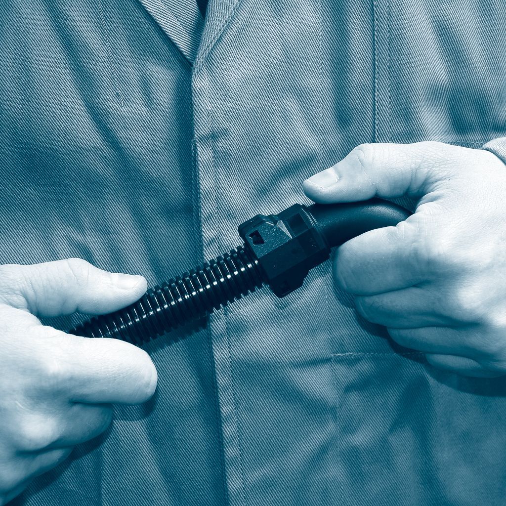
Step 2: Insert the tube into the „closed“ connector as far as it will go (to assemble the connector).
Step 3: Pull the corrugated tube back slightly inside the connector (to latch securely).
Step 4: Move the detent lugs out (to dismantle the connector)
Step 5: Pull the corrugated tube out of the connector.
Step 6: Push the detent lugs in (NORDUC® assembly system ready to use again)
To make your online experience as pleasant as possible,
we use cookies on our website.
You can accept this or make individual settings.
You will find more detailed information in our privacy policy.
Here you will find an overview of all cookies that are used.
You can give your consent to entire categories or have further information displayed and thus select only certain cookies.
Content from external media such as video platforms and social media platforms.
If these cookies are not accepted, access to embedded external media such as YouTube videos is not possible.


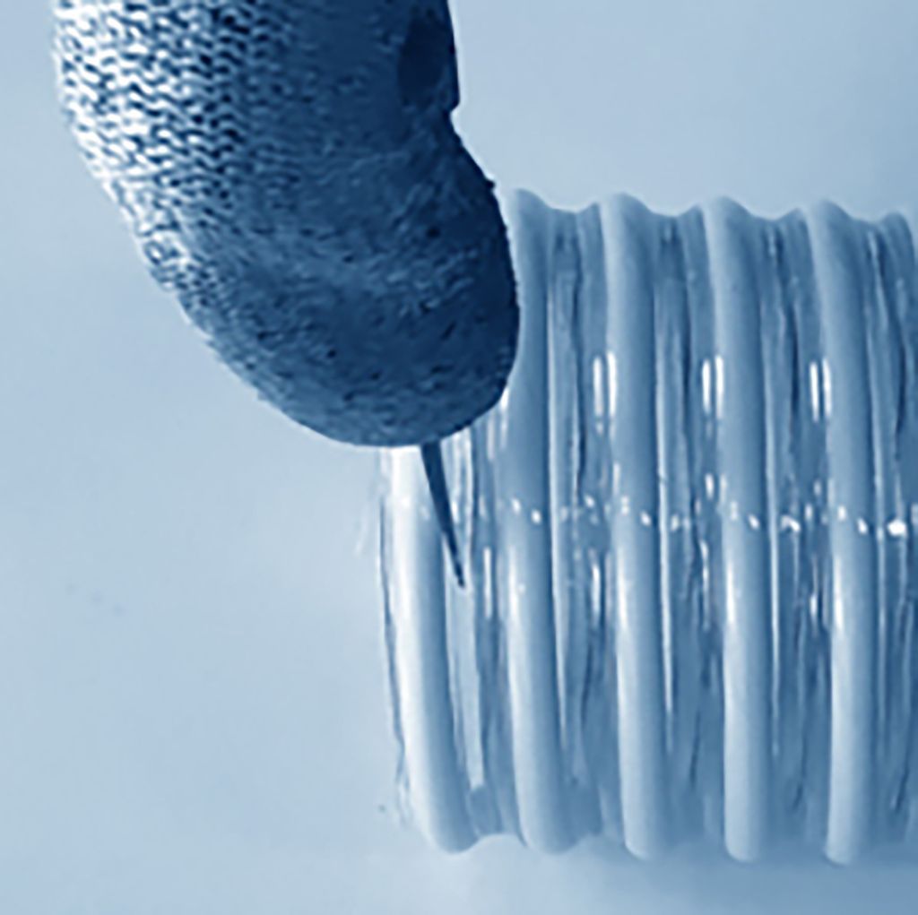
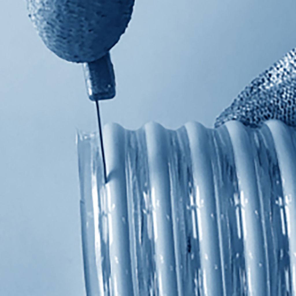 (Detail view)